
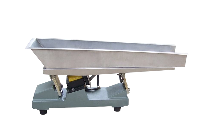
Feeding SERIES
Electromagnetic Feeder
Feed an appropriate bulk material into the next process with the tray, drive and controls specified for the duty.
Equipment selection starts with your material, target separation and process conditions.
01
How the electromagnetic feeding process works
An electromagnetic drive moves material along a feeding tray. Material flow, control requirements and the downstream interface determine the proposed arrangement. This is distinct from parts-orienting bowl feeding.
02
Define the transfer or feeding duty
Discuss the sample and operating conditions before finalizing the configuration.
- Bulk-solid feeding
- Screening-line integration
- Feed-tray and control selection
03
State the required feed behaviour
This enquiry concerns feeding bulk material into a process, rather than orienting small parts in a bowl feeder. Specify the required feed range, upstream hopper conditions and downstream sensitivity to surges. Moving material along a tray does not by itself establish a certified weighing or dosing accuracy.
- Describe how material reaches the tray and changes in hopper level.
- Specify whether feed is continuous, intermittent or signal-controlled.
- Identify build-up, bridging or dust concerns at the transfer point.
04
Review the controller and transfer interfaces
Confirm the actual electrical controller, power supply and start/stop or interlock requirements. Tray form and discharge position must suit the material and receiving machine. A request for a closed-loop dosing system needs a defined measurement and control arrangement beyond a feeder alone.
- Provide tray length constraints and receiving inlet position.
- Ask for permitted controller settings and installation instructions.
- Agree the observation period and collection method used to assess feed consistency.
CONFIGURATION REVIEW
Specify the machine for the task.
| Selection item | Information to confirm |
|---|---|
| Process role | Define material transfer or feed presentation; precision metering is a separate requirement. |
| Material and feed conditions | Supply bulk density, flow behaviour, moisture and temperature where relevant. |
| Interfaces and controls | Agree the route/tray, inlet/outlet, elevations, controller, interlocks and electrical supply. |
| Model and operating data | Use the catalogue table as a starting point; application output and final arrangement are confirmed for the proposed equipment. |
Final technical values, dimensions and performance conditions are confirmed against the proposed equipment and application.
TECHNICAL DATA
Models & specifications
| Model | Nominal capacity (t/h) | Double amplitude (mm) | Vibration frequency (r/min) | Supply voltage (V) | Active power (W) | Weight (kg) |
|---|---|---|---|---|---|---|
| ZW01 | 0.1 | 1.5 | 3000 | 220 | 5 | 4 |
| ZW02 | 0.5 | 1.5 | 3000 | 220 | 8 | 7 |
| ZW03 | 1 | 1.5 | 3000 | 220 | 20 | 12 |
| ZW04 | 2 | 1.5 | 3000 | 220 | 25 | 18 |
| ZW05 | 4 | 1.5 | 3000 | 220 | 30 | 27 |
| ZW06 | 6 | 1.5 | 3000 | 220 | 50 | 45 |
Source condition: nominal capacity is calculated for bulk density 1.6 t/m³. These figures are not a capacity guarantee for a different material or feeding arrangement.
Electromagnetic Feeder
DISCUSS
YOUR TASK
Let's review the application.
Provide the material, separation target and process requirements so that the equipment configuration can be discussed.